
1. Conclusion First: The Primary Criterion for Freeze Dryer Labeling Is Three Parallel Operating Conditions, Not the Minimum Temperature
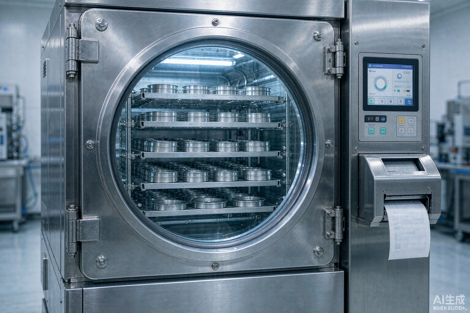
When labeling a freeze dryer, the primary criterion is not whether a label can withstand the -50 °C or -80 °C of the cold trap, but that three mutually incompatible operating condition lines coexist long-term within the same equipment: the cold trap chamber runs year-round at -50 °C (cascade deep-freeze models can reach -80 °C), and after each cycle it must be defrosted and heated; the shelves cycle between -40 °C and +40 °C across primary and secondary drying, and during in-situ sterilization are pushed to 121 °C by pure steam and held for 20-30 minutes; the ambient-temperature layer comprising the chamber housing, glass viewing window and HMI endures disinfectant wiping more than once daily. Compressing the entire machine into a single label material will inevitably leave at least one operating condition line unprotected.
Projects that misplace this criterion fail in a highly consistent manner: selecting material solely by minimum temperature, the cold trap indeed holds, but as soon as the shelves enter in-situ sterilization the labels curl up entirely, and fragments fall into the chamber as foreign-object risk; or conversely, selecting a rigid face stock for high temperature, when applied to the curved inner wall of the cold trap and bellows interfaces, it lifts at the first defrost cycle. The executable sequence should be: first decompose the equipment by installation location, list the temperature range, chemical exposure and geometric curvature of each layer, then select material separately for each layer, and only finally unify printing and ledger conventions.
This article follows this sequence to provide criteria that can be written directly into equipment operating procedures: quantified parameters of the three operating condition lines, a differentiation matrix of six installation locations, geometric calculation of curved-surface sagitta, wrap-around interface treatment for probe leads, matching acceptance of ribbons and barcodes, and a dual-ledger scheme that attaches validation status to a removable layer and asset ledger to a permanent layer. Compliance anchors throughout include ISO 13485:2016 (equipment identification and process validation records), ISO 17025:2017 (temperature probe calibration traceability), GB 19489-2008 (equipment identification involving biological agents), ISO 20387:2018 (biobanking process traceability), GB/T 2792-2014 (peel strength), GB/T 4851-2014 (holding tack), ISO/IEC 15416 (1D barcode print quality) and ISO 7010 W009 (low-temperature warning sign).
2. Decomposing the Freeze Dryer into Three Labeling Layers: Location, Operating Conditions and Failure Modes
The body of a freeze dryer is not a uniform-temperature body. Taking a pilot-scale pharmaceutical freeze dryer as an example, from the product flow perspective it has five stages: pre-freezing, primary drying, secondary drying, stoppering and unloading; but from the labeling perspective, it is three subsystems separated by the chamber and the main vacuum valve: the shelf subsystem that holds the product and controls sublimation, the cold trap water-capture subsystem responsible for solidifying and collecting water vapor, and the ambient-temperature peripheral layer responsible for HMI and appearance management. The temperature envelopes of the three hardly overlap, and chemical cleaning frequencies often differ by an order of magnitude.
| Labeling layer | Typical installation location | Temperature envelope | Chemical exposure | Primary failure mode | Recommended inspection interval |
|---|---|---|---|---|---|
| Deep-freeze layer | Cold trap inner wall, water-capture tray edge, main valve cold end | -50 °C to -80 °C, briefly +40 °C to +80 °C during defrost | Water, ice sublimates, occasional vacuum pump oil mist | Cohesive failure of adhesive and edge lifting after repeated thermal shock | By defrost count; visual re-inspection every six months recommended |
| Heat-transfer layer | Shelf surface edges, tray frames, shelf posts | -45 °C pre-freezing to +40 °C secondary drying, 121 °C during in-situ sterilization | Pure steam, condensate, spilled samples, cleaning media | Print degradation and layer-by-layer peeling after high temperature and humidity | Inspect after each in-situ sterilization and record in batch records |
| Ambient-temperature layer | Chamber housing, viewing window frame, electrical cabinet, nameplate position | 15 °C to 30 °C ambient range | Ethanol, hydrogen peroxide, quaternary ammonium, sodium hypochlorite | Edge curling and print wear from cumulative wiping | Verify quarterly; replace status layer per batch |
3. Cold Trap and Water Capture: The Bidirectional Pull of -50 °C, -80 °C and Defrost Hot Water
The choice of cold trap temperature depends on the lowest eutectic point of the formulation. Most aqueous injectable formulations have eutectic points between -10 °C and -30 °C, and a -50 °C primary cold trap is sufficient; formulations containing a higher proportion of organic solvents with eutectic points below -40 °C require cascade models providing a -80 °C cold trap. For labeling, the real difficulty is not reaching this minimum temperature, but that at the end of a batch the cold trap must be driven up for defrost: common practice is hot water spray or steam heating, with the inner wall briefly rising to +40 °C to +80 °C, then immediately pulled back to deep freeze after defrost.
The impact of this reciprocating cycle on labels can be quantified: assuming one batch per day and 250 batches per year, over ten years the cold trap inner wall undergoes more than 2,500 thermal shocks, each spanning over 110 °C. Any label whose main selling point is unidirectional resistance to a certain temperature needs to be validated under such repeated shock, not judged solely by its minimum tolerance value. The selection criterion should be: prioritize materials that are checked for both the low-temperature grade and the hot-water grade, rather than materials with only the low-temperature grade. In the official BradyLAB (BRD) material guide, among general-purpose products covering all four grades of deep freeze, refrigerator, hot water and autoclave, T629 is the one checked across all four application columns of ambient temperature, test tube, conical tube and microscope slide; prioritize it for the cold trap inner wall and water-capture tray edge.
| Cold trap operating phase | Temperature | Duration per batch | Mechanism of action on label | Material criterion |
|---|---|---|---|---|
| Cooling standby | -50 °C or -80 °C | 1-3 hours | Adhesive continuously embrittles, flexibility decreases | Face stock must remain flexible at low temperature |
| Water capture operation | -50 °C to -80 °C | 12-48 hours | Frost coverage, edges continuously pushed by frost layer | Edge lift resistance prioritized over face stock hardness |
| Defrost drainage | +40 °C to +80 °C | 0.5-2 hours | Rapid temperature rise causes interfacial shear | Must cover hot-water temperature grade |
| Re-cooling standby | Back to -50 °C | 1-2 hours | Second thermal cycle begins | Re-inspect by cycle count, not calendar time |
4. Shelves and In-Situ Sterilization: Adhesion Retention Window Under 121 °C Pure Steam
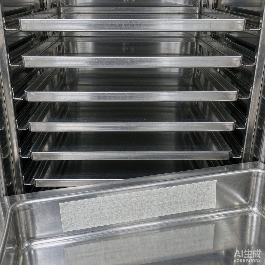
The shelves are the only part of the entire equipment that concentrates all operating conditions. During primary drying the shelves transfer heat to the product, with temperature typically controlled between -40 °C and +20 °C; during secondary drying, to desorb residual water, the shelves rise to +20 °C to +40 °C; at the in-situ sterilization stage, pure steam pushes the chamber and shelves together to 121 °C and holds for 20-30 minutes, with overkill processes typically requiring an F0 of not less than 12. This means labels on the shelves must endure, at the same location, a temperature envelope from -45 °C to +121 °C, spanning 166 °C.
Beyond the temperature extremes, the heating and cooling rates must also be factored in. For a well-controlled freeze dryer, shelf heating and cooling rates are commonly between 0.5 °C and 1.0 °C per minute, requiring 2.8 to 5.5 hours to rise from -45 °C to 121 °C. During this period, thermal expansion of the metal shelves, formation and dissipation of the condensate film, and steam advancing inward along the weakest points of the interface occur simultaneously: the difference in linear expansion coefficients between metal and face stock generates shear at the interface, the condensate film forms a temporary water layer at the interface, and steam propagates along any adhesion defect. Therefore the material criterion for the shelf station is not resistance to 121 °C, but resistance to 121 °C in a wet steam environment—the practical gap between these two statements is very large.
When it comes to specific materials, the autoclave grade must likewise be a hard threshold. In the official table, T459 is an ultra-thin self-laminating construction, with printed content protected by a transparent tail, checked across all four temperature grades, suitable for fixed stations such as shelf posts that contact both deep freeze and steam; when a larger print area is needed for asset numbers, the Lab014-629 nylon cloth label (50 × 30 mm) nylon cloth label (50 × 30 mm) may be selected. Conversely, for locations in the ambient-temperature zone that neither contact deep freeze nor participate in steam sterilization, there is no need to force the use of autoclave-grade material; an ambient-temperature formulation will have a longer service life.
5. Water Vapor Channel, Main Valve and Clean-in-Place: Triple Load of Vacuum, Steam and Alkaline Washing
The water vapor channel and main valve connecting the drying chamber and cold trap are the areas most often missed by labeling schemes. Under vacuum, trace residual gases cause certain low-molecular components to slowly escape and re-deposit at the cold end; during clean-in-place, alkaline cleaning solutions traverse the entire water vapor channel at 40 °C to 80 °C, with common sodium hydroxide concentrations between 0.1 mol/L and 0.5 mol/L. Water-wash resistance does not equal alkaline-wash resistance, and resistance to a single spray does not equal resistance to cumulative weekly spraying.
| Process stage | Medium | Typical parameters | Mechanism of action on label | Exclusion criterion |
|---|---|---|---|---|
| Sublimation stage | Water vapor plus vacuum | Chamber pressure 10 Pa to 30 Pa | Low-molecular components volatilize and deposit at cold end | Formulations lacking solvent-resistance documentation not applicable |
| In-situ sterilization | Pure steam | 121 °C, 20-30 minutes | Interfacial water film heating and shear cause peeling | Materials not checked for autoclave grade excluded from this layer |
| Clean-in-place | Alkaline cleaning solution | 0.1-0.5 mol/L, 40-80 °C | Alkaline attack on face stock and ink layer | Materials without chemical-resistance documentation excluded from this layer |
| Defrost | Hot water or steam | Briefly +40 °C to +80 °C | Thermal shock causes edge lifting | Materials with only a single low-temperature grade excluded from this layer |
6. Ambient-Temperature Layer: Wipe Life of Chamber Housing, Glass Viewing Window and Nameplate Position
The ambient-temperature layer appears simplest but has the most problems, because its failure is not caused by temperature but by cumulative wipe count. Assuming two cleaning wipes before each batch start and 250 batches per year, the housing and viewing window frame endure about 500 wipes per year; disinfectants typically rotate among 75% ethanol, 0.5% hydrogen peroxide, 1000 mg/L quaternary ammonium and 500 to 1000 mg/L sodium hypochlorite.
A feasible approach is to further split the ambient-temperature layer into two layers. The permanent layer carries information unchanged over the full life cycle, such as the unique equipment number, nominal shelf area and installation date; the status layer carries batch-varying information such as cleaned, pending validation, validated and out of service, made with T625 vinyl cloth labels, repositionable, removable and residue-free, torn off and re-applied entirely whenever status changes. Status must be removable, and asset numbers must be permanent—this is a pair of constraints that must be satisfied simultaneously and cannot substitute for each other.
7. Installation Geometry: Curved-Surface Sagitta, Bolted Fasteners and Flat Windows
For the same 60 mm-wide label, applied to a flat electrical cabinet panel versus the curved inner wall of a cold trap, the edge-lift driving force is entirely different. The sagitta formula for a cylindrical surface can directly quantify this: h = R − √(R² − (w/2)²), where R is the radius of curvature of the labeling surface and w is the label width. The larger the sagitta, the farther the label edge is from the wall, the greater the elastic restoring moment toward flatness, and the stronger the edge-lift driving force.
| Installation location | Radius of curvature R | Label width w | Sagitta h | Cutting and application recommendation |
|---|---|---|---|---|
| Electrical cabinet flat surface | Flat | 80 mm | 0 mm | Standard adhesive sufficient; press corners to expel air |
| Cold trap curved inner wall | 200 mm | 60 mm | 2.26 mm | Use cloth-based face stock; press center first, then work outward |
| Chamber outer wall | 320 mm | 60 mm | 1.41 mm | Film type acceptable; leave at least 2 mm margin at edges |
| Main valve body | 60 mm | 25 mm | 1.32 mm | Small size with overlap wrap application, overlap at least 3 mm |
| Probe lead | Diameter 3-6 mm | Wrap width 20 mm | Flat formula not applicable | Wrap along axial direction; use wrap-around material |
Two conclusions can be read directly from this table: First, smaller-diameter locations are less suitable for large-area rigid face stock; for the same 60 mm label, the sagitta on the cold trap inner wall (radius 200 mm) is 2.26 mm, while on the chamber outer wall (radius 320 mm) it is only 1.41 mm; Second, small-diameter locations such as probe leads do not fit the flat formula and must switch to wrap-around application, rather than simply scaling down the flat application method. These two points are also the direct basis for decomposing the equipment into three labeling layers above: sagitta determines face stock flexibility requirements, and the temperature envelope determines temperature grade; the two must be judged separately and then intersected.
8. Temperature Probes and Leads: Interface Treatment for Cross-Condition Wrap-Around Labels
Temperature measurement of freeze dryers is central to performance qualification. Common platinum resistance probes are selected to Class A tolerance, approximately ±0.15 °C, with three-wire configuration starting from an ambient-temperature junction box, one section running through the external environment, one section entering the chamber for positioning, and the probe root also participating in in-situ sterilization. The labeling difficulty on this line is that it spans almost all operating conditions, yet the only available application surface is a lead of 3 mm to 6 mm diameter. The correct approach here is to make the label wrap-around, not flat.
In the official material guide, T509 is a durable vinyl wrap-around material with good conformability, requiring overlap when used in liquid nitrogen environments; its adhesion advantage comes from the face stock's flexibility and the ability to expel air during application, which precisely matches the cylindrical curvature of probe leads. Special note: this material is checked for three temperature grades—deep freeze, refrigerator and hot water—but not autoclave, so the section of the probe root participating in steam sterilization cannot directly use it and must switch to a material checked for autoclave grade. Setting demarcation points by section on the same probe is the standard treatment for such cross-condition interfaces.
9. Printing and Barcodes: Permanent Asset Codes, Temporary Validation Mapping Codes and Batch Codes
Barcodes on freeze dryers serve three completely different purposes, and mixing them is the second most common source of failure. Permanent asset codes are unique over the full life cycle, applied to the equipment exterior and recorded in the equipment ledger; temporary validation mapping codes are short-life labels applied near probes during each temperature distribution validation, removed upon completion; batch codes change with product batches, with variable placement but traceable information. The printing methods and acceptance standards of the three cannot be shared.
| Purpose | Minimum field set | Recommended symbology | Printing method | Retention period |
|---|---|---|---|---|
| Permanent asset code | Equipment number, factory serial number, installation layer | Code 128 | Thermal transfer with matching resin-based ribbon | Full equipment life cycle |
| Temporary validation mapping code | Probe number, mapping coordinates, validation date | Code 128 or Code 39 | Same resin-based ribbon; removed and archived | Removed after validation |
| Batch code | Batch number, shelf number, tray coordinates | Data Matrix | Thermal transfer onto temperature-resistant cloth label | Per product retention requirements |
Barcode print quality itself is accepted by grading per ISO/IEC 15416, with the common practice of an overall grade of not less than 2.5, re-tested once under the aperture of the scanner actually used on site. The most easily underestimated factor here is ribbon matching: for the same high-temperature-resistant material, printing with the wrong ribbon causes print to gray out by the third sterilization cycle. Face stock and ribbon should be accepted as a set, not separately.
10. Performance Qualification Ledger and Periodic Re-Testing: Putting Status in the Removable Layer
Performance qualification of freeze dryers typically includes four sections: shelf temperature uniformity, vacuum system leak rate, cold trap water-capture capacity and sterilization efficacy. Common control indicators include: shelf temperature uniformity controlled within ±1 °C (well-designed models can achieve ±0.5 °C), system leak rate not exceeding the order of one percent millibar·liter per liter per second, and 3 to 9 temperature probes placed on each shelf for distribution testing. These figures are important, but their carrier structure is more important: static fields written on the permanent layer, periodic fields written on the removable layer.
Projects that print changeable information such as the next calibration date directly onto permanent labels inevitably face the same dilemma a year later: either accept that label content does not match the ledger, or tear off and re-apply each one, and the tearing itself introduces version misalignment. Conversely, using a removable status layer to carry due dates, validation status and responsible person, with the permanent layer retaining only immutable fields, repeated tearing and re-application will not touch the traceability chain. This rule and the material layering above are actually two sides of the same principle: put changeable things on a movable layer, and unchanging things on a fixed layer.
11. Standards Anchors: Writing the Criteria into Equipment Operating Procedures
| Standard No. | Correspondence with control points in this article |
|---|---|
| ISO 13485:2016 | Traceability requirements for equipment identification and process validation records, supporting the permanent-layer asset code and operating procedure basis |
| ISO 17025:2017 | Calibration traceability of platinum resistance and temperature measurement systems, supporting the probe labeling and calibration date fields in Section 8 |
| GB 19489-2008 | Equipment identification and status disclosure involving biological agents, supporting the design of the ambient-temperature status disclosure layer |
| ISO 20387:2018 | Traceability requirements for biobanking processes, supporting the batch code layer for freeze-dried live bacteria and culture collection product lines |
| GB/T 2792-2014 | Test method for peel strength of pressure-sensitive adhesive tapes, as a validation means for material selection at each layer |
| GB/T 4851-2014 | Test method for holding tack of pressure-sensitive adhesive tapes, as a means of evaluating upper service life of the deep-freeze layer |
| ISO/IEC 15416 | 1D barcode print quality grading, as the acceptance basis for permanent asset codes in Section 9 |
| ISO 7010 W009 | Low-temperature warning sign, used for the fixed warning layer at cold trap service ports and deep-freeze stations |
12. Implementation Checklist
Compressing the above criteria into executable actions, a freeze dryer labeling project is recommended to proceed in eight steps: Step 1 draw the equipment layering diagram, marking all installation points of the deep-freeze layer, heat-transfer layer and ambient-temperature layer; Step 2 fill in the temperature envelope and chemical exposure list point by point, paying special attention to the water vapor channel and main valve, two locations often overlooked; Step 3 determine by the sagitta formula whether curved surfaces require cloth-based face stock; Step 4 list separately the parts participating in steam sterilization, using only materials checked for autoclave grade; Step 5 select wrap-around application for probe leads and mark the demarcation points that cannot participate in sterilization; Step 6 split permanent fields from variable fields, with all variable fields falling on the removable layer; Step 7 accept face stock and resin-based ribbon as a set, grade per ISO/IEC 15416 and re-scan on site; Step 8 write the visual inspection results three months after first-article operation into the preventive maintenance plan to form a closed loop.
Please note that the material mapping in this article is based on the official BradyLAB (BRD) laboratory and medical series material guide; for models not included in the guide, or where specifications on sale differ from those described in this article, do not infer and apply accordingly—refer to the product specification sheet for specific materials and temperature ranges, and contact the product manager for selection.
Recommended Products
For the three labeling layers and four process conditions covered in this article, the following BradyLAB (BRD) specifications currently on sale are available for selection reference (click to view specifications and request a quote):
- T629 Sample Bank-97 nylon cloth low-temperature label: cold trap inner wall, water-capture tray and deep-freeze stations (¥999/roll)
- Lab014-629/50 × 30 mm liquid nitrogen nylon cloth label: asset ledger positions for shelf posts and trays (¥1890/roll)
- Lab121-459/66.68 × 15.24 mm low-temperature self-laminating label: 121 °C in-situ sterilization stations (Price on request)
- Lab167-509/40 × 25 mm wrap-around label: temperature probe lead cross-condition stations (Price on request)
FAQ
Q1: Can a single label material be used for an entire freeze dryer?
A: Not recommended. Within the same equipment, three operating condition lines coexist—cold trap deep freeze, shelf in-situ sterilization and ambient-temperature housing—with a temperature span exceeding 200 °C. Selecting material solely by minimum temperature will fail during steam sterilization, while selecting solely by maximum temperature will cause lifting on curved surfaces. The correct approach is to decompose into three labeling layers per Section 2 of this article, select materials separately, and then intersect.
Q2: How often should labels on the cold trap inner wall be inspected?
A: It is recommended to use defrost cycle count rather than calendar time as the criterion. Assuming one batch per day and 250 batches per year, about 250 reciprocating thermal shocks from -50 °C to above +60 °C occur per year. A visual inspection every six months is recommended, focusing on whether edges have whitened or lifted, plus a full-machine inspection after each in-situ sterilization.
Q3: Labels on the shelves curl up entirely after sterilization—what could be the cause?
A: There are three common causes: first, the material itself lacks an autoclave grade and covers only the hot-water temperature grade, which inevitably fails under wet steam; second, the shelf surface retains a residual water film or undried cleaning solution before labeling, creating a temporary water layer at the interface; third, insufficient air expulsion during application, allowing steam to advance inward along voids. Check the material grade first, then the application.
Q4: Why can't flat labels be used on temperature probe leads?
A: Probe leads are typically only 3 to 6 mm in diameter, a typical cylindrical surface; flat application creates a cantilever moment at both ends of the label, which quickly curls during thermal cycling. Switch to axial wrapping with an overlap of at least 3 mm at both ends.
Q5: Should validation mapping labels be retained long-term?
A: It is recommended to remove and archive them immediately after validation, not to leave them on the equipment long-term. Mapping labels themselves do not have the operating condition adaptability of the equipment layer; long-term retention will become a source of peeling fragments and contamination in subsequent sterilization cycles. Mapping coordinate information should be recorded in the validation report and electronic ledger.
Q6: When is it recommended to switch to a 2D code format?
A: When print area is limited and fields are long—a typical scenario is placing batch number, shelf number and tray coordinates simultaneously on a small label less than 24 mm wide. Data Matrix has significantly higher information density than 1D barcodes at the same area, with error correction capability, suitable for camera-based reading.
Q7: Can the next calibration date be printed together with the equipment number?
A: Not recommended. The due date is a variable field; once it changes, re-labeling is required, and the re-labeling process introduces transcription errors and version confusion, actually undermining traceability. It is recommended to write the equipment number on the permanent layer and the calibration date on the removable status layer, replacing only the status layer when status changes.