
I. Conclusion First: The Primary Threshold for Mapping Labels Is Temperature Cycling Span, Not Minimum Temperature
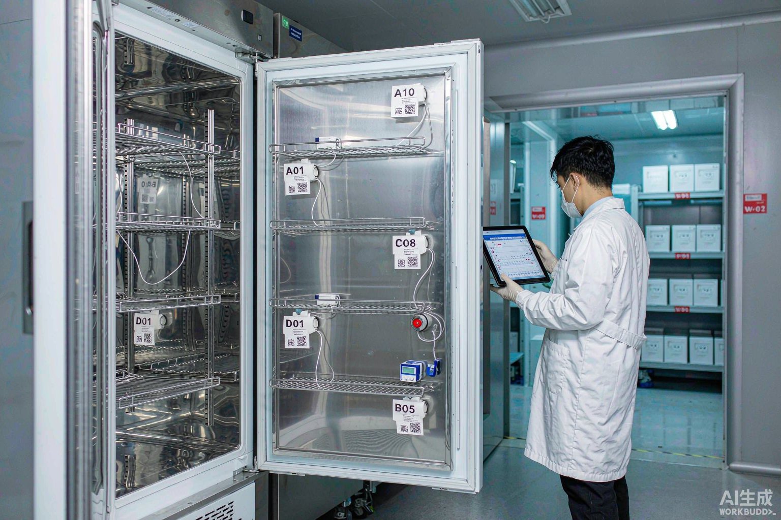
If you are preparing point identification for temperature mapping / temperature distribution study of an ultra-low temperature (ULT) freezer, pharmaceutical cold storage, or LN₂ dewar, reverse the selection sequence first: do not ask "how low does it go" first; ask "how many times per year will this label cycle from minimum temperature back to ambient."
For specimen tube labels in a biobank, the selection logic is "minimum temperature first"—the tube goes into −196 °C LN₂, and the label passes as long as it withstands −196 °C, with almost no temperature fluctuation in between. Mapping labels for cold chain validation are entirely different: they are fixed to the equipment's inner walls or shelves and undergo steady-state low temperature → door opening and warming → defrost warming → re-cooling cycles along with the equipment. A −80 °C upright freezer may experience over 1,000 door openings and 1–4 defrost cycles per year; during each defrost, measurement points inside the chamber rise from −80 °C to above 0 °C or even near ambient, with a single-cycle temperature span exceeding 100 K. In LN₂ vapor-phase tanks, the temperature span at the neck region is even greater during refilling and basket retrieval.
Therefore, the conclusions of this article are threefold:
- First, select the temperature rating by the intersection of "bidirectional extremes"—consider both the steady-state minimum temperature of the equipment and the maximum temperature after defrost/door opening; both endpoints must fall within the material's tolerance range.
- Second, select the face stock by "cycle count" with redundancy—repeated thermal cycling tests the fatigue resistance of the face stock and adhesive layer and the shear resistance of the bonding interface, not single-exposure low-temperature resistance.
- Third, select the construction by "point lifecycle" into two categories—permanent points fixed long-term inside equipment use weather-resistant types; semi-permanent points replaced per validation cycle or requiring residue-free removal use removable types. Do not mix the same material for both.
The material guide table of the BradyLAB (BRD) Lab&HC laboratory medical label series divides temperature into four tiers: LN₂ −196 °C, freezer −80 °C, hot water 100 °C, and autoclave 121 °C, and specifies seven application categories: ambient, microscope slide, cryovial/test tube, conical tube, cell, general purpose, and packaging identification. All selection conclusions below strictly follow this table and introduce no parameters outside it.
II. Why Temperature Distribution Validation Requires "Point Labels" Rather Than Temporary Marks
2.1 Three Irreplaceable Attributes of Validation Points
The core question temperature distribution validation must answer is: within this equipment, do temperatures at all locations during steady-state operation fall within the specified range, and where are the hottest and coldest points. To make this conclusion reproducible, each measurement point must have three attributes:
Uniqueness—each measurement point has only one number throughout the entire validation cycle; the mapping diagram coordinates in the validation report, the data logger channel number, and the physical on-site location correspond one-to-one. Once numbers are duplicated or illegible, the traceability of the entire validation report is broken.
Persistence—point identification must survive the entire validation cycle. A typical validation cycle is 24 consecutive hours to 7 days (some annual or seasonal validations are longer), during which labels must not detach, curl, or fade. If point identification detaches mid-validation, the mapping consistency of that round cannot be self-demonstrated.
Reproducibility—during the next re-validation, routine monitoring point adjustment, or re-validation after equipment relocation, probes must be placed at the same physical location. This is why point identification cannot be "temporarily taping a note with 1, 2, 3": temporary marks disappear during cleaning, defrosting, and de-icing, and the second validation's mapping positions differ from the first, making data incomparable.
2.2 Point Drift: The Most Common Hidden Cause of Validation Failure
In practice, when temperature distribution validation is challenged, it is mostly not a probe accuracy issue but point drift—during the second validation, the probe hangs on the adjacent shelf or is 20 cm farther from the return air inlet. Since measurement points near the evaporator and return air inlet in a −80 °C freezer may inherently differ by 3–8 K from the geometric center point, moving a point by tens of centimeters can completely flip the "hottest point" conclusion.
The most cost-effective means of countering point drift is to create physical permanent point markings on the equipment's inner walls and shelves and incorporate them into the validation protocol's mapping diagram. This is the entire subject of this article.
III. Mapping Geometry: From Equipment Volume to Point Count
3.1 Two-Layer Mapping Method: Uniform Grid + Key Point Overlay
The general approach to point placement is two-layer overlay: first divide the equipment interior geometrically into a uniform grid, placing one measurement point at the center of each grid cell; then overlay "key points" outside the grid—locations physically most likely to deviate from the specified range.
Key points typically include six categories: locations near door seals and door bodies (most directly affected by door opening), directly in front of evaporator air outlets (coldest point), near return air inlets (potentially hottest), the equipment geometric center (representing the main volume), heat transfer surfaces near inner and outer walls (affected by ambient temperature), and locations near heat-generating components (such as interior lighting, defrost heating elements, circulation fans).
It is also necessary to distinguish no-load validation from full-load validation. Under no-load conditions, air circulation is good and temperature uniformity is typically better than under full load; under full load, goods block airflow, making localized dead zones likely. Regulatory requirements and actual practice typically require both states, or at least coverage of the most unfavorable state. The corresponding point labels must withstand both states—under full load, labels may be compressed and rubbed by cryoboxes and racks, which directly determines whether abrasion-resistant face stock is needed.
3.2 Mapping Examples for Three Typical Equipment Types
The quantities below are examples to illustrate mapping logic and label consumption estimation; actual point counts must be determined by equipment volume, geometric structure, number of risk points, and the organization's validation protocol and applicable regulations.
| Equipment Type | Typical Volume/Specification | Temperature Range (Steady State) | Example Mapping | Temperature Cycling Source |
|---|---|---|---|---|
| Upright ULT freezer | 300–800 L | −86 °C to −80 °C | Top/middle/bottom three layers × front/middle/rear = 9 points + 1 door point = 10 points | 5–15 door openings daily, 1–4 defrosts annually |
| Pharmaceutical cold storage / refrigerated warehouse | 10–100 m³ | 2 °C to 8 °C | Three layers by height, zoned by plan, 1–2 points per zone, plus 1 point each at door, supply air outlet, and return air inlet | Daily loading/unloading door openings, automatic defrost cycles |
| LN₂ vapor-phase storage tank | Neck / vapor-phase zone | −190 °C to −150 °C | Below neck, neck, vapor-phase zone top/middle/bottom 1 point each | Refilling and basket retrieval cause severe neck temperature rise |
As can be seen, the commonality among the three equipment types is not "all very cold" but all periodically return to near ambient. LN₂ tanks are especially prone to misjudgment: many assume that since the interior is at −196 °C year-round, only the most low-temperature-resistant material is needed. In reality, the neck region surges from −190 °C to near ambient within minutes during lid opening and retrieval, making it the location with the most severe temperature cycling in the entire equipment—and typically where labels fail first.
IV. Point Coding: One Code Linking Validation Reports, Routine Monitoring, and Re-validation
4.1 Code Structure and Length
Point codes should use a segmented structure that packs "equipment—zone—layer—sequence" into a single short code, for example:
ULT03-R2S1P05 — ULT03 indicates ULT freezer No. 3, R2 indicates zone 2 (e.g., door side/wall side), S1 indicates shelf layer 1, P05 indicates measurement point No. 5. A 14-character alphanumeric string fully describes the physical location.
Keeping code length within 12–16 characters is a practical range: sufficient to express segmented information without making the barcode size exceed the label format. Beyond 20 characters, the number of modules required for DataMatrix rises significantly, and label size and print resolution must increase accordingly.
4.2 Why Point Codes Should Prioritize DataMatrix Over 1D Barcodes
The available format for point labels is typically very limited—the affixable area on equipment inner walls, shelf crossbeams, and cables is often only 25–50 mm wide. At this scale, the trade-off between 1D barcodes and DataMatrix can be calculated directly using size formulas.
The symbol width of Code 128 is approximately (11n + 35) × X + quiet zones on both sides, where n is the number of data characters and X is the module width. For a 14-character code with X = 0.25 mm: width = (11×14 + 35) × 0.25 = 47.25 mm, plus 2.5 mm quiet zones on each side gives approximately 52.25 mm, which already exceeds the available width of most point labels; moreover, 1D barcodes have bar height requirements, and insufficient bar height directly affects first-read rate.
DataMatrix is a square symbol with capacity graded by module count:
| Symbol Size | Numeric Capacity (digits) | Alphanumeric Capacity (characters) | Side Length at X=0.40 mm | Side Length at X=0.50 mm |
|---|---|---|---|---|
| 10×10 | 6 | 3 | 4.0 mm | 5.0 mm |
| 12×12 | 10 | 6 | 4.8 mm | 6.0 mm |
| 14×14 | 16 | 10 | 5.6 mm | 7.0 mm |
| 16×16 | 24 | 14 | 6.4 mm | 8.0 mm |
| 18×18 | 36 | 20 | 7.2 mm | 9.0 mm |
| 20×20 | 44 | 28 | 8.0 mm | 10.0 mm |
A 14-character point code falls within the 18×18 capacity range (20 alphanumeric characters). At X = 0.50 mm, the symbol side length is 9.0 mm; with 1–2 mm quiet zones on all sides, a 35 mm × 25 mm label still has ample space for human-readable point number, equipment name, and labeling date. If the symbol is reduced to X = 0.40 mm, the side length is 7.2 mm, allowing use on narrower strip labels, but requiring higher print resolution and reader resolution.
Symbol quality assessment may reference the grading methods of ISO/IEC 15416 (1D barcode print quality) and ISO/IEC 15415 (2D barcode print quality). Under low-temperature conditions, frost and condensation on the label surface significantly reduce symbol contrast, so the printing process must use resin-based ribbon; ordinary wax-based ribbon will smudge after wiping with condensation water, dropping symbol grade to unusable.
V. Material Selection: Tier-by-Tier Comparison Against the Official Material Guide Table
5.1 Official Temperature Tier Matrix
The table below follows verbatim the BradyLAB Lab&HC laboratory medical cryogenic/ULT/solvent-resistant label material guide table, listing only commonly used materials relevant to cold chain validation mapping. "√" indicates the official designation that the material is suitable for the corresponding temperature tier.
| Material No. | Material & Construction | LN₂ −196 °C | Freezer −80 °C | Hot Water 100 °C | Autoclave 121 °C | Ambient |
|---|---|---|---|---|---|---|
| T629 | Nylon cloth label, easy to apply, high/low temperature resistant, good conformability | √ | √ | √ | √ | √ |
| T459 | Ultra-thin polyester, self-laminating label with clear tail, transparent window for liquid level observation | √ | √ | √ | √ | — |
| T509 | Durable vinyl label, suitable for wrap-around, requires overlap in LN₂ environments | √ | √ | √ | — | — |
| T439 | 6-color cryogenic label, pre-printed color band at top for quick differentiation | √ | √ | √ | — | — |
| T419 | Bright white PET material, for cryovials and microcentrifuge tubes | — | — | — | — | √ |
Two easily misunderstood specifications require special clarification:
T419 has a temperature boundary of −40 °C. The official specification is "resistant to environments above −40 °C." Pharmaceutical cold storage (2–8 °C) and freezer storage (−25 °C to −15 °C) fall within this range and may use it; however, −80 °C ULT freezer inner walls and LN₂ tank points are not within its official designation range, and materials officially designated for both LN₂ and freezer tiers should be selected instead.
T509 is a wrap-around construction. Its official application description is "suitable for wrap-around, good conformability, requires overlap when used in LN₂ environments," and it is not a flat laminating construction. This characteristic corresponds precisely to wrap-around identification of probe cables rather than flat labeling on chamber walls; when used in LN₂ environments, overlap treatment is required per official specifications.
5.2 Permanent Points, Semi-Permanent Points, and External Reference Positions
Classifying point labels by lifecycle into three categories can significantly reduce material misuse:
| Point Type | Typical Location | Lifecycle | Temperature Exposure | Selection Key Points |
|---|---|---|---|---|
| Permanent point | Freezer/cold storage inner walls, shelf crossbeams, rack uprights | Equipment lifetime, spanning multiple validation cycles | Cycles with equipment throughout | Material designated for both LN₂ and freezer tiers and ambient tier; face stock must be abrasion-resistant and wipe-resistant |
| Semi-permanent point | Temporary additional points, seasonal validation add-on points, transition points after equipment relocation | Single validation cycle or 1 year | Same as above | Also select by intersection of minimum and maximum temperatures; handle adhesive residue per cleaning procedures upon replacement |
| External reference position | Exterior door panel, door frame, beside equipment nameplate, point reference table board | 1–3 years | Essentially ambient, occasionally affected by cleaning disinfectants | Ambient tier sufficient; bright white PET face stock optional; format may be enlarged to A5 board size |
Among the three, permanent points are the only ones that must be selected by "bidirectional extremes": they must withstand both the steady-state minimum temperature and the maximum temperature after defrost/door opening, and maintain bonding through hundreds of thermal cycles per year.
5.3 Bonding Interface: Effect of Different Liner Materials on Labels
There are four common affixing surfaces inside cold chain equipment, with significantly different surface energies and thermal expansion characteristics that directly determine whether labels will curl.
| Affixing Surface | Common Location | Surface Characteristics | Effect on Bonding | Handling Recommendations |
|---|---|---|---|---|
| Brushed / mirror stainless steel | Upright freezer inner walls, cold storage panels | Relatively high surface energy, but prone to residual rolling oil and detergent film | Incomplete cleaning leads to insufficient initial peel strength | Degrease with 75% ethanol, wipe dry, apply at ambient and roll-press, let stand 24 h before cooling |
| Powder-coated steel | Shelves, racks | Medium surface energy, coating has microscopic roughness | Differential expansion between coating and substrate at low temperature transfers to adhesive layer | Select cloth-based face stock with good conformability; roll-press edges and corners thoroughly |
| ABS liner | Refrigerated chamber liners, some medical refrigerators | Medium-high surface energy | Silicone-containing detergent residue severely weakens bonding | Prohibit silicone-containing detergents; use neutral detergents and rinse thoroughly |
| PP / PE liner | Some low-temperature chambers, transport box liners | Low surface energy, approximately 29–31 mN/m | Ordinary pressure-sensitive adhesives struggle to form effective wetting | Prefer cloth-based face stock with good conformability; conduct small-sample trial affixing if necessary |
Adhesion performance may be comparatively tested at incoming inspection or selection stage per the methods specified in GB/T 2792-2014 (Determination of 180° peel strength for adhesive tapes) and GB/T 4851-2014 (Test method for holding power of adhesive tapes). Note that these two standards specify ambient test conditions; to assess low-temperature performance, specimens should be placed at low temperature for a specified duration, removed, and tested immediately, with test conditions documented in the validation records.
VI. Application and Installation
6.1 Wrap-Around Identification of Probe Cables
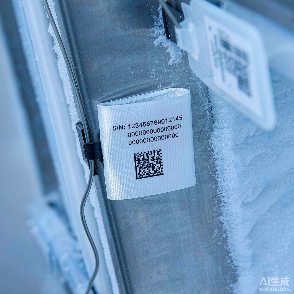
Temperature validation probes typically have 1–3 m cables leading from inside the chamber to the external data logger. The cables themselves must be identified; otherwise, ten cables exiting through the door seal cannot be distinguished by channel. Flat labels affixed to cables quickly detach due to cable bending and cable/door seal compression. The correct approach is wrap-around identification: wrap the label around the cable once, with both ends overlapping to form a flag; the overlap area is not printed, allowing position adjustment.
T509 is a vinyl label officially designated as "suitable for wrap-around" with good conformability, suitable for this purpose; when used in LN₂ environments, overlap treatment is required per official specifications. Wrap-around identification should be placed at two locations: 30–50 mm from the probe end (identifying the point number corresponding to the probe) and at the cable end after exiting the chamber (identifying the channel number), with matching codes at both locations for easy verification.
6.2 Color-Code Layering: Separating Equipment, Temperature Tier, and Validation Year
When a laboratory has multiple units of the same equipment type, or when the same unit has undergone multiple annual validations, distinguishing by number alone can cause confusion. Color-code layering using pre-printed color band material is the simplest approach: T439 is a 6-color pre-printed cryogenic label with a pre-printed color band at the top, officially intended for "quick identification and differentiation of laboratory container types." Applied to mapping scenarios, colors can encode temperature tiers (e.g., blue for 2–8 °C cold storage, purple for −80 °C freezer, white for LN₂ vapor phase) or encode validation year, allowing instant determination of which validation round a label belongs to upon opening the door.
Once the color-code scheme is established, it must be written into the validation protocol and kept consistent; changing color rules mid-course causes more serious confusion than having no color code at all.
6.3 Printing and Ribbon
Point labels must be printed by thermal transfer with resin-based ribbon. The reason is that direct thermal labels generally darken or fade under low-temperature high-humidity conditions, disinfectant wiping, and defrost warming, while wax-based ribbon imprints have insufficient rub resistance and may lose characters after a single cleaning wipe. The BradyLAB LAB laboratory-specific cryogenic ribbon BRL-110-BK (110 mm × 300 m, black) is configured for such applications.
After printing, a first-article inspection is recommended: read the symbol grade using a barcode verifier per ISO/IEC 15416 / ISO/IEC 15415 methods, and proceed to batch printing only after the grade is acceptable. Under low-temperature conditions, it is recommended to set the symbol grade target one level higher than ambient scenarios, because frost and condensation will consume part of the contrast margin.
VII. Compliance Anchors and Record Closure
7.1 Standard Number Cross-Reference
Compliance requirements related to temperature distribution validation point identification are distributed across several systems; the table below may be used for reference during selection and protocol preparation:
| Standard / Regulation | Requirements Relevant to Point Identification | Specific Impact on Label Selection |
|---|---|---|
| ISO/IEC 17025:2017 | Facilities and environmental conditions, equipment control and metrological traceability | Point numbers must correspond one-to-one with equipment ledgers and calibration/validation records |
| ISO 20387:2018 | Biobank equipment and storage condition control | Location identification within storage equipment must support specimen traceability |
| ISO 15189:2022 | Medical laboratory quality and competence requirements, including pre-examination procedures and equipment | Temperature monitoring points in refrigerated/frozen specimen storage equipment must be reviewable |
| GSP (Good Supply Practice for Pharmaceutical Products) | Temperature monitoring and validation requirements for refrigerated/frozen drug storage and transport | Mapping positions must be fixed and reproducible, with supporting point reference documentation |
| GB 19489-2008 / WS 233-2002 | General requirements for laboratory biosafety / General biosafety guidelines for microbiological and biomedical laboratories | Storage equipment involving pathogenic specimens requires point labels resistant to disinfectant wiping |
| GB/T 2792-2014 | Determination of 180° peel strength for adhesive tapes | Peel strength comparison may be conducted during selection |
| GB/T 4851-2014 | Test method for holding power of adhesive tapes | Evaluate long-term hanging weight and creep resistance |
| ISO/IEC 15415 / ISO/IEC 15416 | 2D / 1D barcode symbol print quality grading | Determine symbol grade acceptance threshold and printing parameters |
7.2 Matching Re-validation Cycle with Label Life
The replacement cycle of point labels should be no shorter than the re-validation cycle. If equipment undergoes temperature distribution validation annually, permanent point labels should be designed for a service life of at least 12 months; if the validation cycle is every 3 years, labels should be designed for 36 months, with label condition checked and an integrity confirmation recorded at each validation.
It is recommended to add a clause to the validation protocol: before each validation begins, verify the integrity and readability of all point labels; for points found detached, curled, or illegible, re-affix and photograph for evidence before placing probes. This action turns "point consistency" into an auditable record rather than relying on on-site personnel memory.
VIII. Six-Step Implementation SOP
Step 1: Compile equipment ledger and temperature ranges. Register each unit's equipment number, type, volume, steady-state temperature range, defrost method, and door opening frequency. The output of this step is the "minimum–maximum" dual endpoint for each unit, against which all subsequent selection is based.
Step 2: Determine mapping plan and produce mapping diagram. Map points using uniform grid plus key point overlay, number each on the diagram, and output a point coordinate table.
Step 3: Define coding rules and symbology. Determine a 12–16 character segmented code structure, look up DataMatrix size and module width based on code length, and confirm it fits within the selected label format.
Step 4: Select material by dual endpoints. Against the official material guide table, select material designated as suitable for both the minimum temperature tier and the maximum temperature tier; for low-temperature equipment inner walls, prioritize cloth-based face stock such as T629 that is designated for all four tiers—LN₂, freezer, hot water, autoclave—plus ambient; use wrap-around type for cables; use ambient tier for external reference positions.
Step 5: Application and curing. Clean the affixing surface, degrease with 75% ethanol, wipe dry, apply at ambient temperature and roll-press, let stand 24 h to allow the adhesive layer to establish initial tack, then cool the equipment to operating temperature. Skipping the standing period and cooling directly is one of the main causes of early label detachment.
Step 6: Photograph for archiving and incorporate into validation protocol. Photograph each point with the point label and surrounding reference objects, and archive together with mapping diagram coordinates as the basis for position comparison during re-validation.
IX. Failure Modes and Troubleshooting
| Symptom | Most Likely Cause | Troubleshooting and Resolution |
|---|---|---|
| Label corners lifting, gradually detaching entirely | Not degreased during application, or cooled immediately after application without standing | Re-apply after thorough degreasing, let stand 24 h at ambient before cooling; switch to cloth-based face stock with better conformability |
| Label brittle at low temperature, face stock cracking | Face stock does not cover the equipment's minimum temperature tier | Re-select per minimum temperature tier, using material designated for both LN₂ and freezer tiers |
| Adhesive oozing at label edges after defrost, position shift | Adhesive layer not resistant to high-temperature end, exceeding material's specified upper temperature limit | Re-select per "bidirectional extremes," confirming the high-temperature end is also within designated range |
| Characters blurred, barcode unscannable | Wax-based ribbon or direct thermal paper used, or excessive cleaning/wiping | Switch to resin-based ribbon thermal transfer printing; avoid barcode area during cleaning |
| Insufficient symbol contrast after frost formation | Insufficient symbol grade margin, module width too small | Increase module width, raise symbol grade acceptance threshold, enlarge label format if necessary |
| Label compressed and worn under full load | Point located in goods collision path, face stock abrasion resistance insufficient | Relocate point to a position less prone to compression, or apply transparent protective film |
| Points misaligned during re-validation | Label loss causing position memory failure | Replenish permanent point labels and photograph for archiving; incorporate into validation protocol |
Recommended Products
For the label materials and application scenarios covered in this article, the following BradyLAB (BRD) products are available for selection reference (click to view specifications and request a quote):
- Lab112-629/35 × 25 mm biobank cryovial EP tube microscope slide −196 °C LN₂ nylon cloth label (¥1490/roll)
- Lab014-629/50 × 30 mm biobank cryovial EP tube microscope slide −196 °C LN₂ nylon cloth label (¥1890/roll)
- Lab096-629/80 × 60 mm biobank cryovial EP tube microscope slide −196 °C LN₂ nylon cloth label (¥999/roll)
- Lab208-509/25.4 × 63.5 wrap-around biobank straw LN₂ classification label (Price on request)
FAQ
Q1: Can I just use cryovial labels for temperature distribution validation mapping?
The material can be shared, but the selection criteria differ. Cryovial labels remain at constant low temperature with specimens long-term and only need to cover the minimum temperature end; mapping labels are fixed to equipment and undergo "low temperature—defrost warming—re-cooling" cycles with the equipment, so they must cover both minimum and maximum temperature ends. Additionally, mapping labels must withstand cleaning/wiping, full-load compression, and personnel contact, typically requiring higher abrasion resistance. Therefore, it is recommended to re-verify material tier against bidirectional extremes rather than directly adopting cryovial selection conclusions.
Q2: Can removable material be used for point labels to facilitate point changes?
It depends on point type. External reference positions and temporary additional points that are not in low-temperature zones or serve only a single validation may use removable type, leaving no adhesive residue upon replacement. However, permanent points inside equipment are not recommended to use removable type: removable adhesive low-temperature holding power is typically lower than permanent adhesive, making it more prone to failure under repeated thermal cycling, and permanent point detachment would destroy validation reproducibility. Selection should first confirm that the material is officially designated as suitable for the equipment's minimum temperature tier.
Q3: Why do point labels at the LN₂ tank neck region detach so easily?
Because the neck is the location with the greatest temperature span in the entire equipment. During basket retrieval and refilling, the neck rises from approximately −190 °C to near ambient within minutes, then undergoes severe cooling on return—this high-frequency, large-span cycling is an extreme test of adhesive fatigue resistance. Neck points should use material designated for both LN₂ and ambient tiers, with thorough roll-pressing during application, sufficient standing time, and a quick integrity check after each lid-opening operation.
Q4: Should point codes use 2D or 1D barcodes?
Prioritize DataMatrix. For a 14-character code, Code 128 at X = 0.25 mm requires a symbol width of approximately 52 mm, which with quiet zones on both sides exceeds most point label formats, and limited bar height affects first-read rate; DataMatrix 18×18 at X = 0.50 mm has a side length of only 9