
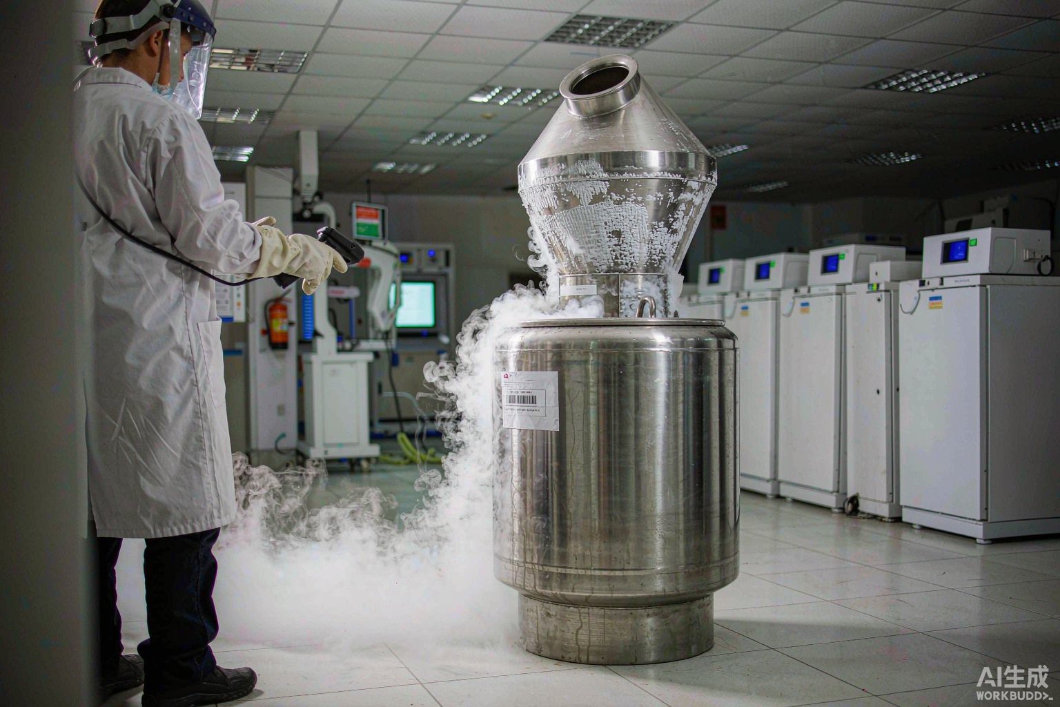
How to choose labels for LN₂ tanks? The conclusion: the primary criterion is not -196 °C, but the temperature gradient across a single label, plus how many times it will be subjected to refilling and retrieval actions. The conventional approach in biobanks for labeling cryovials is to "select material by the lowest temperature across the entire process," but this rule becomes inaccurate when applied to LN₂ tanks—labels on the tank are not immersed in liquid nitrogen as a whole. The BRD BradyLAB Lab series approach to equipment-level identification on LN₂ tanks is: break the tank into three identification layers—tank outer shell, neck tube and neck plug, and lift rod and basket—and select materials layer by layer according to operating conditions, rather than applying the same product to the entire tank.
1. Conclusion first: the primary criterion for LN₂ tank labels is not -196 °C
The boiling point of liquid nitrogen at one atmosphere is -195.8 °C, with a density of approximately 0.808 kg/L—these are the baseline figures for all LN₂ scenarios. However, the outer shell of a vacuum-insulated vessel is not a low-temperature surface. Product standards for medical liquid nitrogen storage systems explicitly require that the outer surface below the upper head of the vacuum vessel shall not exhibit beaded or running condensation, nor shall ice or frost form. In other words, a well-functioning LN₂ tank has an outer shell that is a dry, ambient-temperature surface during normal operation and can be touched with bare hands.
True low temperatures occur in only two places: inside the neck tube, and on the lift rod and basket when withdrawn. This creates a condition unique to LN₂ tanks—a single label spans a temperature gradient of nearly 200 °C. Take a label on the lift rod handle as an example: the handle end is at ambient temperature year-round (around 20 °C), while the immersed end undergoes a complete cycle from -196 °C (liquid phase) or no higher than -180 °C (gas-phase storage zone) back to ambient temperature each time it is inserted and withdrawn.
Pressure-sensitive adhesive failure mostly does not occur at the coldest end, but in the gradient transition zone. The reason is that the coefficient of linear expansion differs between the face stock and the metal being labeled: 304 stainless steel is approximately 17.3×10⁻⁶/°C, aluminum approximately 23×10⁻⁶/°C. If the coefficient of linear expansion of the face stock and the adherend differ by 10×10⁻⁶/°C, over a 100 mm length subjected to a 200 °C temperature differential, the accumulated relative displacement is approximately 0.2 mm. This magnitude is sufficient to cause high-stiffness film face stocks to lift at the edges, while flexible cloth-based materials can absorb it through their own deformation.
2. An LN₂ tank is not one identification object, but three
Treating the entire tank as a single object for material selection is the most common mistake in LN₂ tank labeling. The three identification layers have completely different normal temperatures, primary stresses, and replacement frequencies, and should be selected separately.
| Identification layer | Location | Normal temperature | Primary stress | Replacement frequency | Selection key points |
|---|---|---|---|---|---|
| Layer 1: Tank outer shell | Front of cylinder outer wall, at eye level 1.3–1.5 m | Ambient, dry (standard requires no condensation or frost) | Mechanical scratching, cart collisions, repeated disinfectant wiping | Low, every 1–2 years or upon status change | Look at chord-height rebound and wipe resistance, not temperature resistance |
| Layer 2: Neck tube and neck plug | Tank opening, neck tube outer wall, neck plug top surface | Alternating between -190 °C and ambient | Refilling thermal shock, cold vapor flushing when opening, water film from melting frost | Medium, per seal maintenance cycle | Leave pressure-relief gap, avoid frost surfaces, no new application within 24 h before/after thermal shock |
| Layer 3: Lift rod and basket | Lift rod handle, basket crossbar, cryorack | One end at ambient for hand-holding, one end immersed at -196 °C or no higher than -180 °C | Cross-temperature-zone thermal cycling, frequent friction, overlap edge peeling | High, per cryobox and basket replacement | Select by cycle count, wrap with head-to-tail overlap |
3. Counterintuitive: LN₂ tanks are the identification objects with the least geometric constraint and the greatest cycle constraint in a biobank
On cryovials, fine tubes, and microcentrifuge tubes, the primary constraint is always geometry—the tube circumference determines the wrappable arc length, and a label slightly too wide will not lie flat. But LN₂ tanks are the opposite: a φ500 mm tank has a circumference of approximately 1570 mm, and an 80 mm wide label occupies only 5.1% of the circumference—there is almost no width constraint.
However, geometry has not completely exited; it has taken a different form: chord-height rebound. Treat the label as a rigid chord applied to a circular arc; the gap between the edge and the curved surface is:
h = R − √(R² − (w/2)²), where R is the tank radius and w is the label width
| Tank outer diameter | Radius R (mm) | Label width w (mm) | Chord height h (mm) | Edge gap interpretation |
|---|---|---|---|---|
| φ300 mm (common for 10–30 L small tanks) | 150 | 80 | 5.43 | Large gap; film types will inevitably lift at edges |
| φ500 mm | 250 | 80 | 3.22 | Still requires flexible face stock |
| φ660 mm | 330 | 80 | 2.43 | Flexible cloth-based material can absorb |
| φ800 mm (large gas-phase tank) | 400 | 80 | 2.00 | Ample margin, but high-stiffness film still not recommended |
Compare with cryovials: a φ12.5 mm cryovial has a radius of only 6.25 mm, and a 25 mm wide label with w/2 = 12.5 mm is already greater than R—flat application is geometrically impossible; wrapping is the only option.
The conclusion is direct: the edge-lifting driving force for tank labeling comes from chord-height rebound, and the smaller the diameter, the greater the chord height. This magnitude cannot be absorbed by the adhesive layer of high-stiffness PET films; only flexible cloth-based materials can conform. Therefore, the first choice for LN₂ tank outer shells and lift rod positions is not film types, but the T629 nylon cloth material, which has good conformability and is checked for all four temperature ratings in the official guide.
4. From static evaporation rate to refill date: a field that is miscalculated every day
Static evaporation rate is a core specification on the LN₂ tank nameplate; it determines the daily loss under "static, unopened" conditions. Common compliance ranges are: storage-type 10 L tanks no greater than 0.5 L/d, 50 L tanks no greater than 0.9 L/d, 100 L tanks no greater than 1.2 L/d, transport-type 30 L tanks no greater than 1.5 L/d. Test conditions are strict: ambient temperature 23±2 °C, relative humidity 40%–60%, static for 14 days, with the first 7 days as the stabilization period; only the average daily evaporation of the latter 7 days is the result.
The problem is that converting static evaporation rate directly into a refill date requires at least three corrections:
Correction 1: Do not use a full tank. Refill should occur when the liquid level is at 1/3–1/2 remaining; completely depleting before refilling will cause the internal temperature to rise, and sudden injection of liquid nitrogen will cause a rapid temperature differential change in the tank body. Usable volume = effective capacity × (1/2 to 2/3).
Correction 2: Dynamic consumption is far greater than static. Each opening volatilizes approximately 50–100 mL of liquid nitrogen; 5 openings per day adds an additional 0.25–0.5 L/d.
Correction 3: Environment and liquid level. When room temperature exceeds 30 °C, evaporation increases by 30%–50%; when the liquid level is below 20% of total capacity, the liquid-phase coverage area of the inner vessel decreases, and evaporation loss rises by approximately another 20%.
| Calculation basis | Formula | Refill cycle | Deviation from nominal |
|---|---|---|---|
| Static ideal value (nameplate basis) | 50 L ÷ 0.20 L/d | 250 days | Baseline |
| Retain 1/3 liquid level | 33.3 L ÷ 0.20 L/d | 167 days | ×0.67 |
| Add 5 openings per day | 33.3 L ÷ (0.45–0.70) L/d | 48–74 days | ×0.29–0.44 |
| Add ambient above 30 °C | 33.3 L ÷ (0.59–1.05) L/d | 32–56 days | ×0.19–0.34 |
That is, the 167 days calculated from the nameplate static evaporation rate differs from the actual refill cycle of 32–74 days by 2.3–5.2 times. Therefore, if "next refill date" is printed on the tank label, it must be determined by dynamic consumption and must never copy the static value; moreover, the refill date is a field that will be repeatedly rewritten and should be made into a removable, rewritable status layer rather than engraved into a permanent layer.
Two directly actionable criteria: first, if daily usage evaporation exceeds 1.5 times the static evaporation rate, it is judged as abnormal evaporation; the troubleshooting order is seal cap aging → opening frequency → environment; second, weight-method verification: total weight to refill ≈ empty tank weight + effective capacity × 0.808 kg/L × 1/3.
5. Neck tube and neck plug: three prohibited zones—pressure relief, frost, and thermal shock
The neck tube is the location on an LN₂ tank with the harshest operating conditions and the easiest place to misapply labels. Three prohibited zones must be written into the SOP.
Prohibited zone 1: Do not block the pressure-relief passage. The liquid-to-gas volume expansion ratio of liquid nitrogen at 20 °C is 1:694; 1 L of liquid nitrogen can vaporize into approximately 700 L of nitrogen gas. The neck plug itself is not a seal; its function is to reduce heat exchange while retaining pressure-relief capability. Any application method that wraps a closed ring between the neck plug and neck tube creates a risk of physical explosion. A continuous pressure-relief gap must be left between the label and the neck plug. For tanks with pressure monitoring, the internal pressure safety threshold is typically in the 0.05–0.1 MPa range.
Prohibited zone 2: Do not apply to frost surfaces. After refilling and after opening, frost forms on the outer wall of the neck tube; when the frost layer melts, a water film forms at the interface, and pressure-sensitive adhesive can hardly establish effective adhesion on a water film. The method is to wait for the frost layer to naturally recede, allow the surface to return to ambient temperature, and wipe dry before applying, or move the identification position up to the tank opening ring platform above the neck tube. For flat positions in cold zones such as basket crossbars, use a freezer flat-surface material such as T429, and follow the application requirement of at least 3 mm head-to-tail overlap.
Prohibited zone 3: Do not newly apply within the thermal shock window. During refilling, the tank opening temperature drops from ambient to near liquid nitrogen temperature within tens of seconds, with ΔT of approximately 200 °C. Pressure-sensitive adhesives typically require 24–72 h to reach final bond strength; if the adhesive layer undergoes such shock before completing wetting, interfacial stress will directly pull the label off. Therefore, do not newly apply labels within 24 h before or after refilling, and do not perform adhesion acceptance at the tank opening immediately after refilling.
One safety boundary must also be stated clearly: the statutory safety labels for liquid nitrogen as a refrigerated liquefied gas are provided by the gas supplier with the container; what BradyLAB (BRD) provides is a device-level self-applied dynamic management layer. The two are not substitutes, and the dynamic layer must not cover, obscure, or replace the statutory layer. Regarding oxygen deficiency risk, an oxygen content below 19.5% is considered an oxygen-deficient environment; 10 kg of liquid nitrogen instantaneously evaporating in a 10 m³ space can reduce oxygen concentration from 20.9% to approximately 13%. Tank labeling must also not obscure oxygen deficiency alarms and ventilation ports.
6. Lift rod and basket: a 200 °C gradient on a single label
Lift rods commonly have a diameter of 8–12 mm, corresponding to a circumference of 25.1–37.7 mm. The wrap-direction length of a wrap-around label must be greater than or equal to the circumference plus overlap allowance. Taking a 25.4×63.5 mm wrap specification as an example, the 63.5 mm wrap-direction length covers the φ12 mm lift rod circumference of 37.7 mm and still leaves 25.8 mm, fully meeting the requirement of at least 3 mm head-to-tail overlap; the excess can also wrap a second turn for double-layer protection.
For lift rod wrapping, the first choice is T509 vinyl wrap-around material, which has good conformability; when used in LN₂ environments, head-to-tail overlap is required.
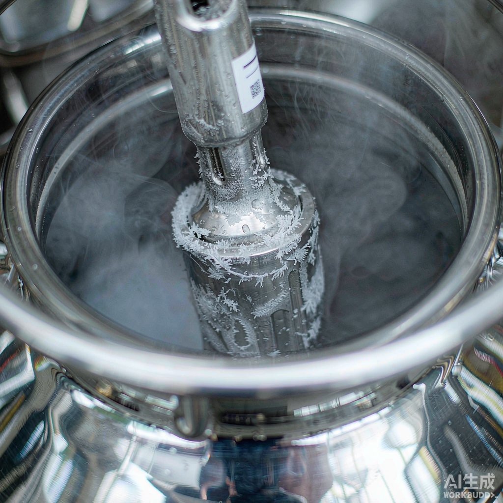
The most typical failure mode of lift rods is "handle end intact, immersed end lifted." This is not insufficient temperature resistance of the material, but thermal cycle accumulation: the handle end is at ambient year-round, while the immersed end goes through a complete cycle each time it is withdrawn and returned. If a lift rod is inserted and withdrawn 250 times per year, that is 500 thermal cycles over two years. Therefore, the selection criterion for the lift rod position is cycle count, not single-exposure tolerance.
The product standard for automated liquid nitrogen storage systems provides three directly quotable figures: in gas-phase mode, the sample storage zone temperature should be no higher than -180 °C; during tube picking and transfer, sample temperature should be no higher than -150 °C; when the working chamber relative humidity is below 2%, code-reading accuracy should be no less than 99.9%. This shows that in automated tanks, readability in the tube-picking zone is inherently guaranteed; the real bottleneck is insufficient bar height of 1D codes on the curved surface of thin rods, not the environment.
7. Official material temperature rating matrix: who can survive on the tank
The table below is transcribed item by item from the official Lab series material guide, listing only the ratings relevant to the three identification layers of LN₂ tanks. The key to interpreting LN₂ tank equipment-level labeling is: look at the checks across all four temperature ratings, not the single temperature number printed on the product name.
| Material code | Face stock structure | LN₂ -196 °C | Freezer -80 °C | Hot water 100 °C | Autoclave 121 °C | Ambient | Applicable position on tank |
|---|---|---|---|---|---|---|---|
| T459 | Ultra-thin polyester self-laminating, with transparent tail window | ✓ | ✓ | ✓ | ✓ | — | Beside tank viewing window, where printed content needs protection |
| T629 | Nylon cloth label, good conformability | ✓ | ✓ | ✓ | ✓ | ✓ | Tank outer shell, lift rod handle, basket crossbar (primary) |
| T429 | Freezer flat-surface label, at least 3 mm head-to-tail overlap on frozen surfaces | ✓ | ✓ | ✓ | ✓ | — | Flat cold zones such as baskets and cryoracks |
| T439 | 6-color pre-printed cryogenic label, pre-printed color on top | ✓ | ✓ | ✓ | — | — | Tank color-code zoning, responsible-person zoning |
| T509 | Vinyl wrap-around, good conformability | ✓ | ✓ | ✓ | — | — | Lift rod wrapping (first choice, overlap required in LN₂ environments) |
| T419 | Glossy white PET, officially rated for -40 °C and above | — | — | — | — | ✓ | Not applicable to any low-temperature position on the tank |
| T329 | Matte white PP self-adhesive, officially rated for -40 °C | — | — | — | — | ✓ | Not applicable to any low-temperature position on the tank |
The last two rows are the most easily misused in this table. In the official guide, the temperature column for T419 and T329 is uniformly marked as -40 °C and above, with only the ambient rating checked; however, the gas-phase storage zone temperature of an LN₂ tank is no higher than -180 °C, and the liquid phase is even lower. Once the target position will contact such cold vapor, T419 and T329 are not candidates; applying them to the tank outer shell and then subjecting them to long-term cold vapor flushing at the tank opening is a typical cross-rating misuse.
The reverse should also be noted: T629 is the only material in the official guide that is checked for all four application categories—ambient, microscope slides, cryovials, and conical tubes—and for all four temperature ratings—LN₂, freezer, hot water, and autoclave. The LN₂ tank scenario of "a single label spanning three temperature ratings" is essentially made for it.
8. Encoding field set and code type selection
The tank main label is recommended to carry 9 fields: tank number, storage mode (gas phase V / liquid phase L), content category, responsible person, last refill date, next refill date, nominal static evaporation rate, measured dynamic consumption, tank position coordinates (room-row-column). The last four are variable fields and are recommended to be placed on a removable status layer.
| Position | Available format | Code type | Size calculation | Conclusion |
|---|---|---|---|---|
| Tank outer shell | 80×60 mm | Code 128 | Module count M = 11n + 35; when n=24, X=0.25 mm, symbol width is 74.75 mm, plus 5 mm quiet zones on both sides totals 79.75 mm | Too tight; change to n≤20 (68.75 mm) or reduce X to 0.19 mm (60.6 mm) |
| Tank outer shell | 80×60 mm | DataMatrix | 20×20 modules, X=0.40 mm, side length 8.0 mm | Ample format margin, suitable for long encodings |
| Lift rod φ12 mm | 10 mm wide label, chord height 2.68 mm | DataMatrix | 20×20 modules, X=0.25 mm, side length 5.0 mm; symbol edge is 2.5 mm from center, gap at that point is 0.55 mm | Good conformity in central area, feasible |
| Lift rod φ8 mm | Chord height too large | 1D code | Insufficient bar height, and w/2 approaches R | Not recommended; use narrower format or apply to basket crossbar instead |
There is an easily overlooked detail here: the geometric margin of the tank label is large, but the digit count of Code 128 grows quickly. Each additional digit of n increases symbol width by 11 modules, which is 2.75 mm at X=0.25 mm. Therefore, a 24-digit encoding already approaches the limit of an 80 mm label; either compress the number of encoding digits, reduce X, or switch to 2D. It is recommended to fix the digit count at the encoding rule design stage rather than adding digits as you go.
Tank color-code zoning can be combined with T439 6-color pre-printed material, using the pre-printed color on top to distinguish gas-phase tanks from liquid-phase tanks, different responsible persons, or different content risk levels—much faster than reading plain text.
9. Eight-step application SOP
Step 1, determine the layer: first determine whether this is the tank body layer, neck tube layer, or lift rod layer; the materials and processes for the three layers are not interchangeable.
Step 2, position: for the tank body layer, take the center of the front curved surface at eye level 1.3–1.5 m; avoid the base, original nameplate, valves, oxygen deficiency alarms, and ventilation ports; leave a continuous pressure-relief gap for the neck plug.
Step 3, clean: wipe with isopropyl alcohol or 75% ethanol to remove fingerprint oils and disinfectant residue, and dry for 3–5 min; frost positions must wait for the frost layer to recede and return to ambient temperature before proceeding.
Step 4, calculate: determine the next refill date based on dynamic consumption, do not copy the nameplate static evaporation rate; record both the nominal static value and the measured dynamic value as two fields.
Step 5, select code: when using Code 128 on the tank body, keep the encoding digit count within 20 digits, or reduce X to 0.19 mm; use DataMatrix 20×20 on the lift rod.
Step 6, print: use a resin-based cryogenic ribbon; after changing materials, printing temperature, speed, and pressure must be reset and verified with a proof; do not reuse old parameters.
Step 7, apply: for the tank body layer, roll from one end to the other to expel air; for the lift rod layer, wrap with at least 3 mm head-to-tail overlap, with the overlap position avoiding the barcode symbol area.
Step 8, rest and acceptance: rest at ambient temperature for 24 h before allowing the label into the cold zone; for adhesion, perform retained-sample re-verification following the 180° peel strength approach of GB/T 2792 and the holding tack approach of GB/T 4851; barcode quality shall be graded per ISO/IEC 15416 (1D) or ISO/IEC 15415 (2D); below grade C shall not be accepted into inventory.
10. Three types of failure and troubleshooting order
| Phenomenon | Primary suspect | Verifiable criterion | Action |
|---|---|---|---|
| Tank label edge lifting | Chord-height rebound caused by excessive face stock stiffness | Gap is uniform along the width direction, value falls within 2–5 mm | Switch to flexible cloth-based material, or change to two narrow strips side by side |
| Lift rod immersed end lifting, handle end intact | Thermal cycle accumulation, not insufficient single-exposure temperature resistance | Insertion/withdrawal records exceed 300 times | Switch to wrap-around with overlap, shorten replacement cycle |
| Barcode unreadable | Print quality rather than material | ISO/IEC 15416 grade below C | Reset print parameters, switch to resin-based ribbon, increase X dimension |
| Refill overdue | Date determined by static evaporation rate | Measured dynamic consumption ÷ static nominal > 1.5 | Change to dynamic determination, move date to removable status layer |
| Neck plug area label curling | Water film interface after frost melting | Still curls after re-application following frost recession | Move to tank opening ring platform, avoid frost surface |
Recommended Products
For the three identification layers of LN₂ tanks and corresponding materials covered in this article, the following BradyLAB (BRD) products are available for selection reference (click to view specifications and request a quote):
- Lab096-629/80×60mm Biobank cryovial EP tube microscope slide -196 °C LN₂ nylon cloth label (¥999/roll)
- Lab121-459/66.68×15.24mm Laboratory conical tube cryogenic cryovial PET self-laminating label (Price on request)
- Lab208-509/25.4×63.5 Wrap-around cryovial biobank fine tube LN₂ classification label (Price on request)
- Lab032-429/30×20mm Biobank cryovial microscope slide PET polyester label cryogenic adhesive (Price on request)
- Lab084-439/30×15mm Biobank cryovial polyester label cryogenic biological sample bank classification label (Price on request)
- BRL-110-BK BradyLAB LAB laboratory-specific cryogenic ribbon, black, 110mm×300m (Price on request)
FAQ
Q1: Do LN₂ tank outer shells really need dedicated cryogenic labels?
It depends on which layer you are labeling. The tank outer shell is a dry ambient-temperature surface; the real constraints are chord-height rebound and wipe resistance, not low-temperature resistance. However, positions such as the neck tube and lift rod that enter cold vapor or the liquid phase must be selected for the -196 °C rating. In practice, the simplest approach is to use a flexible cloth-based material checked for all four temperature ratings uniformly across the entire tank, avoiding layer-by-layer selection errors.
Q2: Can the refill date be calculated from the nameplate static evaporation rate?
It cannot be calculated directly. The test conditions for static evaporation rate are 23±2 °C, relative humidity 40%–60%, and static for 14 days without opening. In actual use, opening, high ambient temperature, and low liquid level combine, and the real cycle is typically only 1/3 to 1/5 of the static basis. It is recommended to print both the nominal static value and the measured dynamic value on the label, and determine the date based on the dynamic value.
Q3: Why do lift rod labels always stay intact at the handle end but lift at the immersed end?
This is cumulative thermal cycle damage, not insufficient single-exposure temperature resistance. The handle end is always at ambient temperature, while the immersed end goes through a 200 °C temperature differential cycle each time it is withdrawn and returned. The solution is to switch to wrap-around style with at least 3 mm head-to-tail overlap, and set a mandatory replacement cycle based on insertion/withdrawal count rather than waiting for it to fall off.
Q4: Can labels be applied directly to the neck plug?
Not recommended, and it must be ensured that the pressure-relief passage is not blocked. The liquid-to-gas volume expansion ratio of liquid nitrogen is 1:694; the neck plug's function is to reduce heat exchange while retaining pressure-relief capability. A wrap that forms a closed ring carries a risk of physical explosion. When identification of the neck plug or tank opening is needed, move the identification position up to the tank opening ring platform and leave a continuous gap.
Q5: Is there a difference in label selection between gas-phase and liquid-phase tanks?
For material ratings, they can be uniformly selected for the liquid phase -196 °C, which naturally covers gas-phase conditions. The real difference is in encoding and color coding: in gas-phase mode, the sample storage zone temperature is no higher than -180 °C, and the liquid phase is even lower. The two tank types have different content risks and retrieval procedures; it is recommended to use 6-color pre-printed material for mode zoning to avoid mixing.
Q6: Is RFID worth it for tank labeling?
Tanks are few in number, fixed in position, and infrequently inventoried; the benefit of RFID is less obvious than on cryovials and sample boxes. A more cost-effective approach is to use large-format asset codes with Code 128 or DataMatrix on the tank body, and reserve the RFID budget for the cryovial layer inside the tank. If tank-level automatic identification is truly needed, refer to HF band solutions per ISO 15693 / ISO 18000-3.
Q7: How should labeling be adjusted for tanks with reduced vacuum?
After vacuum decay, condensation or even frost will appear on the tank outer surface, which no longer meets the product standard's anti-condensation requirements and is a sign of equipment failure; address the tank itself first rather than changing labels. However, when temporarily labeling a faulty tank, follow the frost-surface rules for the neck tube layer: wait for the surface to return to ambient temperature and wipe dry before applying, and shorten the re-inspection cycle. A 10%–20% increase in evaporation for tanks in use for 3–5 years is normal aging; if daily evaporation exceeds 1.5%, special inspection should be arranged.
Related Compliance Standards
- ISO 20387:2018 Biobanking—General requirements—traceability chain requirements for tank position encoding and sample localization
- ISO 17025:2017 General requirements for the competence of testing and calibration laboratories—equipment-level identification and metrological traceability
- ISO 15189:2022 Medical laboratories—Requirements for quality and competence—pre-examination procedures and sample identification
- GB 19489-2008 Laboratories—General requirements for biosafety—control of low-temperature and oxygen deficiency hazards
- WS 233-2002 General biosafety guidelines for microbiological and biomedical laboratories
- GB/T 2792-2014 Pressure-sensitive tape—180° peel strength test—tank adhesion acceptance
- GB/T 4851-2014 Pressure-sensitive tape—holding tack test—long-term adhesion acceptance
- ISO/IEC 15416 and ISO/IEC 15415 Barcode print quality assessment—1D and 2D grading
- ISO 7010 W009 Biohazard symbol—content risk level identification
- ISO 15693 / ISO 18000-3 HF 13.56 MHz RFID—alternative for tank-level asset automatic identification
For more materials and specific applications, please contact the product manager for selection; specific available specifications are subject to the product datasheet.